Getting Started With Emio
Emio is a parallel deformable robot. Together with the desktop application Emio Labs, this hands-on platform provides a practical introduction to the concepts of compliant and deformable robotics.
Discovering Emio
The robot features a structure composed of four servo motor-actuated deformable legs connected together. It comes equipped with a depth camera and a set of accessories, including multiple deformable legs and connectors, all stored in a dedicated drawer.
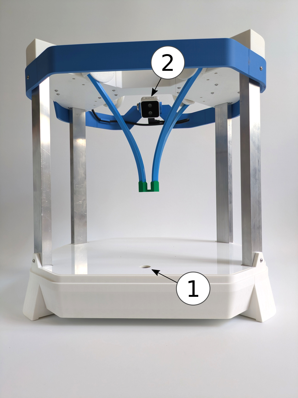
Emio features two distinct configurations, as shown in the images below:
- Extended Configuration: In this setup, the legs point downward, enabling it to perform tasks such as pick-and-place.
- Compact Configuration: Here, the legs are oriented upward, facilitating easier interaction with the robot.
Connecting Emio to Your Computer
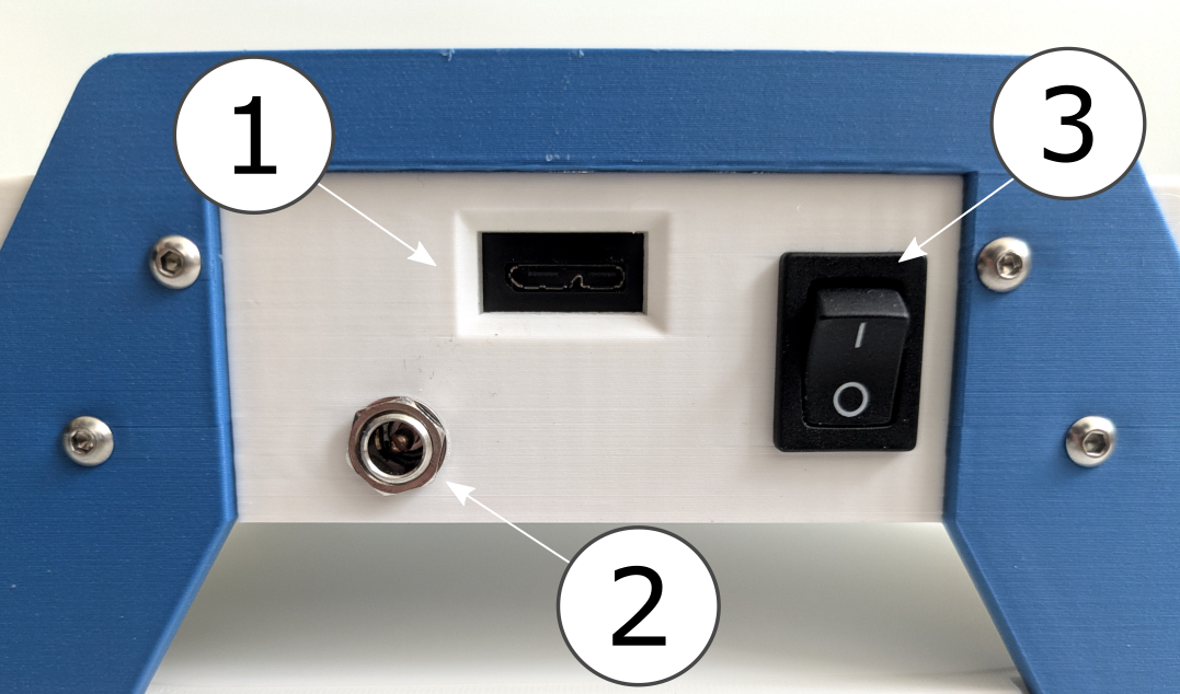
You will find a USB cable in the drawer to connect the robot to your computer. The robot also has a power supply and a switch. To connect Emio to your computer:
- Plug the USB cable into the USB port of Emio (see Figure 2),
- Connect the other end of the USB cable to your computer,
- Plug the power supply into the power port of Emio (see Figure 3),
- Turn on the switch to power the robot (see Figure 3).
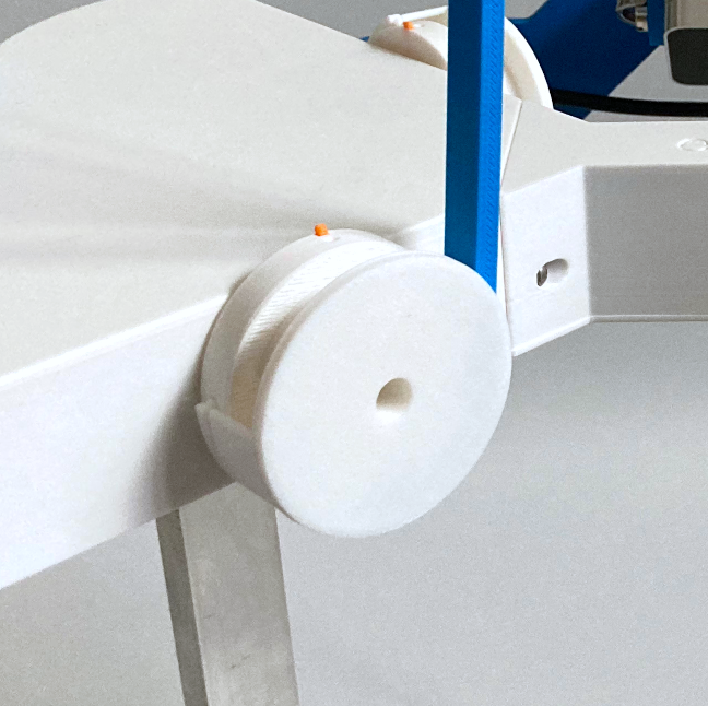
Attaching Legs to Motors
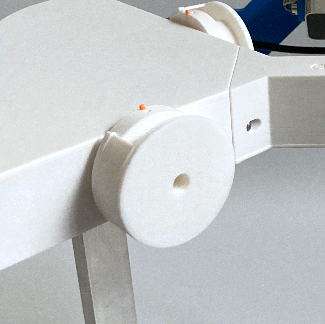
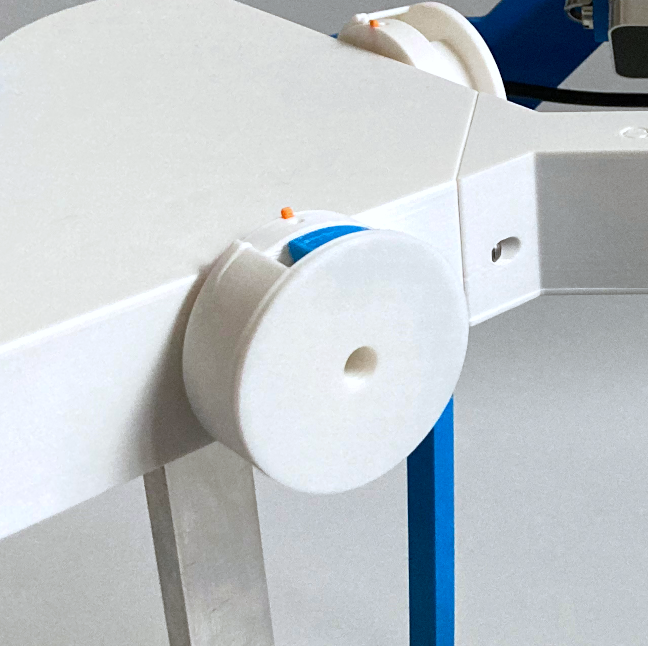
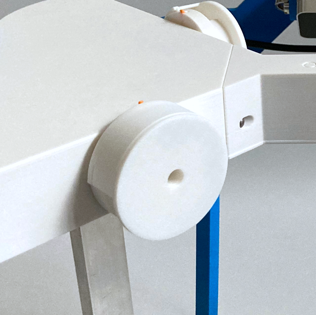
Each motor is equipped with a drum and a cap for connecting a leg.
To attach a leg to a motor:
- Find the zero position of the motor is indicated by the orange marker pointing upward,
- Simply rotate the cap until you can set the leg into the desired orientation,
- Once the leg is in place, rotate the cap again to lock it.
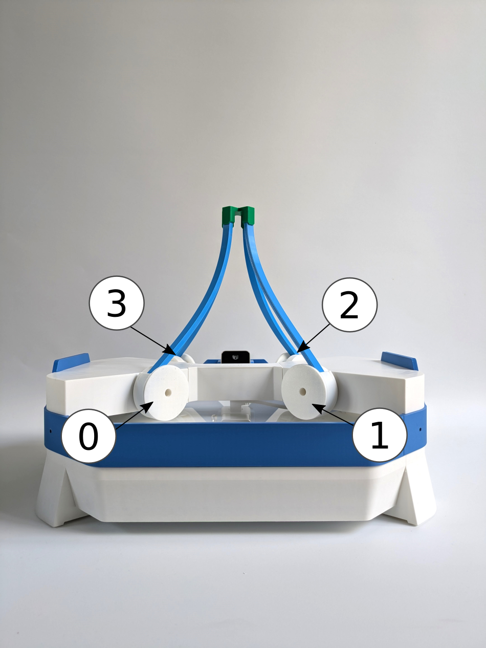
Throughout the lab sessions, you will be instructed to configure Emio into specific setups. Simply follow the provided instructions by clicking on Set up Emio. We use colors to refer to the legs and connectors, and numbers to identify the motors.
Calibrating the Camera
The calibration allows to calculate the transform from the camera image, to 3D points into the simulation reference frame. The Emio API (included with Emio Labs) comes with a default calibration, but it can vary based on if the camera has been moved. If you notice a large difference between the simulation and reality markers, you might need to re-calibrate the camera.
Set up Emio for the Calibration
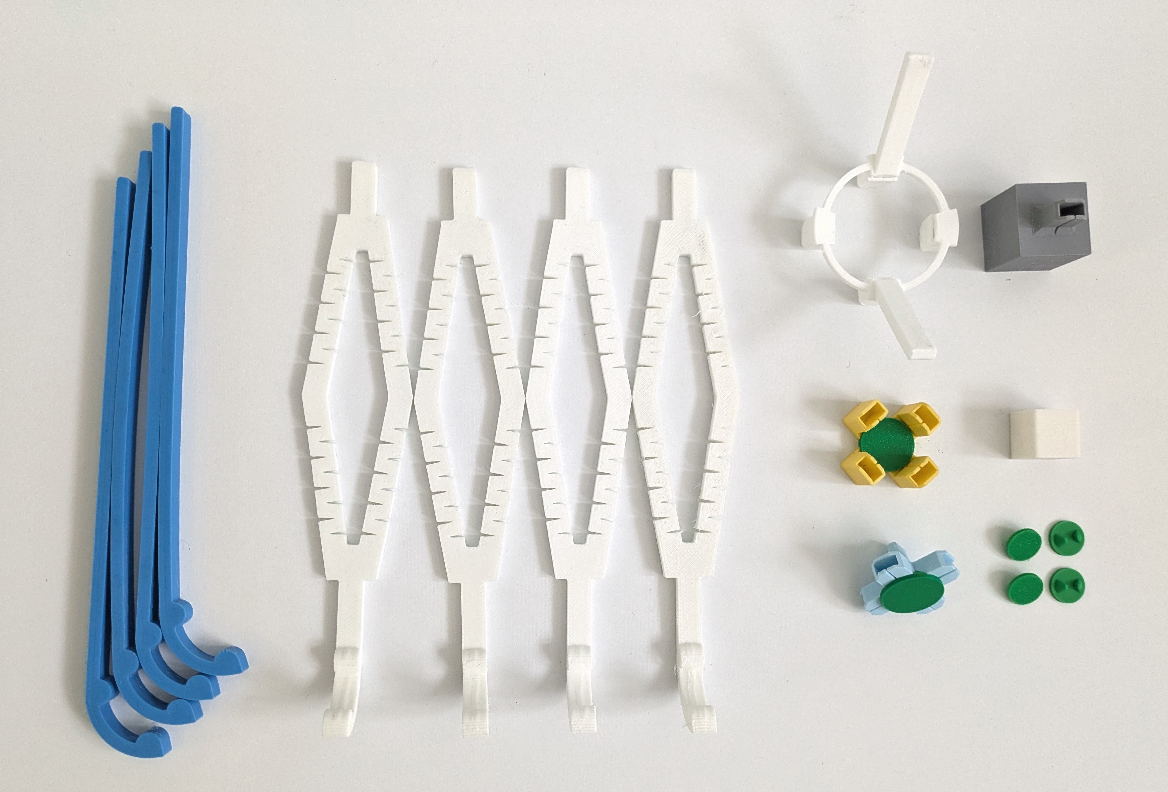
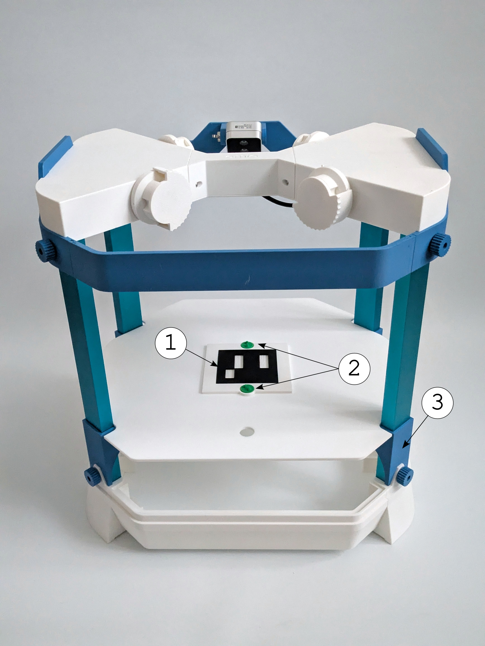
You will need (see the image to the right):
- The Aruco marker
- Two green markers
- The blue elevators to raise the platform
To set up Emio for calibration, follow these steps:
- Raise the platform with the blue elevators.
- Place the Aruco marker on the platform, arrow facing the camera.
- Insert two green markers into the Aruco marker slots.
- Connect Emio to the computer and power supply.
- Turn on Emio.
The calibration marker normally comes with Emio but you can 3D print it using either:
- the whole marker file (requires a multicolor 3D printer)
- the support file and the Aruco marker file
The Aruco marker should be printed in black and the support in white for better performance.
Start the Calibration
Calibration can be done using several methods: with Emio Labs or with the Emio API.
- Emio Labs
- Emio API
The easiest way to start the calibration is to use the SOFA Robotics interface from Emio Labs:
- Open Emio Labs
- Go to the
Sandboxpage - Select the
Camera Calibrationsection - Run the simulation by pressing the SOFA button in the section
- Press the Play button to start the simulation
- Toggle the robot connection button to connect to the robot
Alternatively, you can start the calibration using Emio API. From a terminal with a Python executable that has emioapi installed, run:
python -m emioapi calibrate
For more information, go to the Emio API documentation and follow the instructions to start the calibration process.
Calibration Process
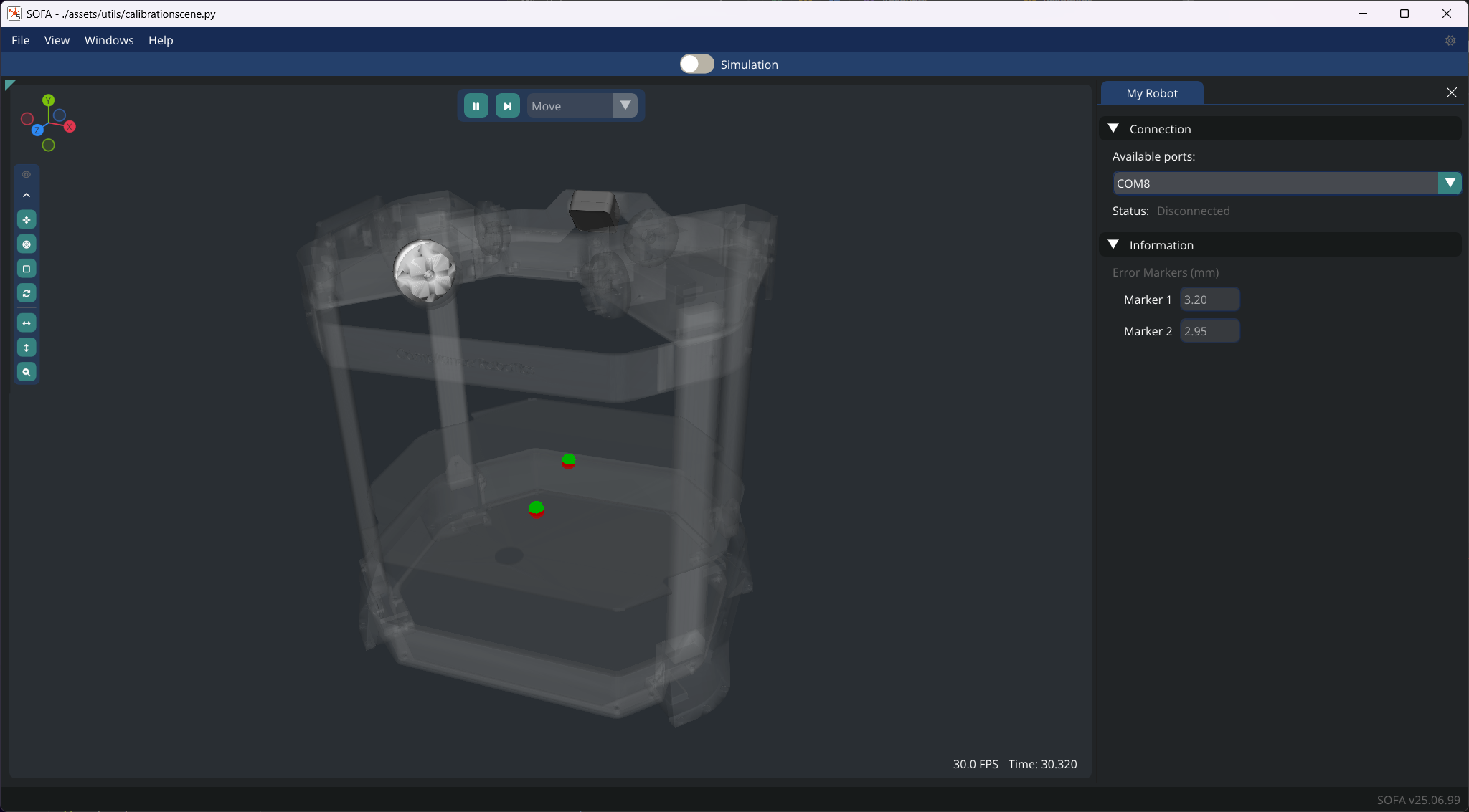
Regardless of the method you use to start the calibration, the process will start by opening several windows, including a Calibration window and a RGB Frame window.
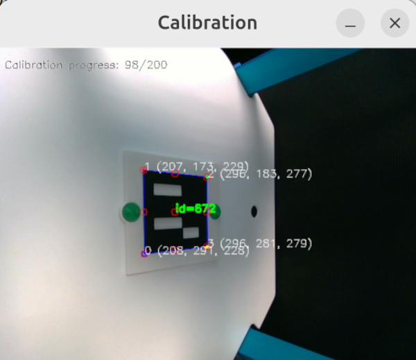
The Calibration window displays the corners and other points detected by the camera.
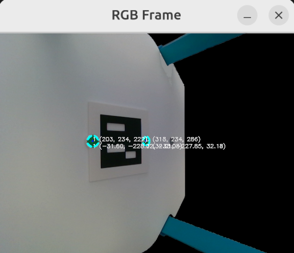
The RGB Frame window displays the 3D position of the two markers in the frame of the camera (first line) and in the simulation frame (second line).
The calibration ends when the Calibration window closes and the RGB Frame window displays the position of the the two markers.
To make sure the calibration is successful, you can check the simulation coordinates of the markers in the RGB Frame window:
- The top marker should be at around
(32, -230, 32) - The bottom marker should be at
(-32, -230, -32)
In the simulation, if used, the green markers (i.e. what the camera is tracking) should be at the same positions as the red markers (i.e. theoretical positions). The actual error for each marker can be seen in the Information collapsible menu in the My Robot window. You can expect an error of around 2-4 mm for each marker.
Once the calibration is done, you can close the SOFA window or Ctrl+C if you used Emio API. The saved calibration will be used for all the following use of the Emio API.